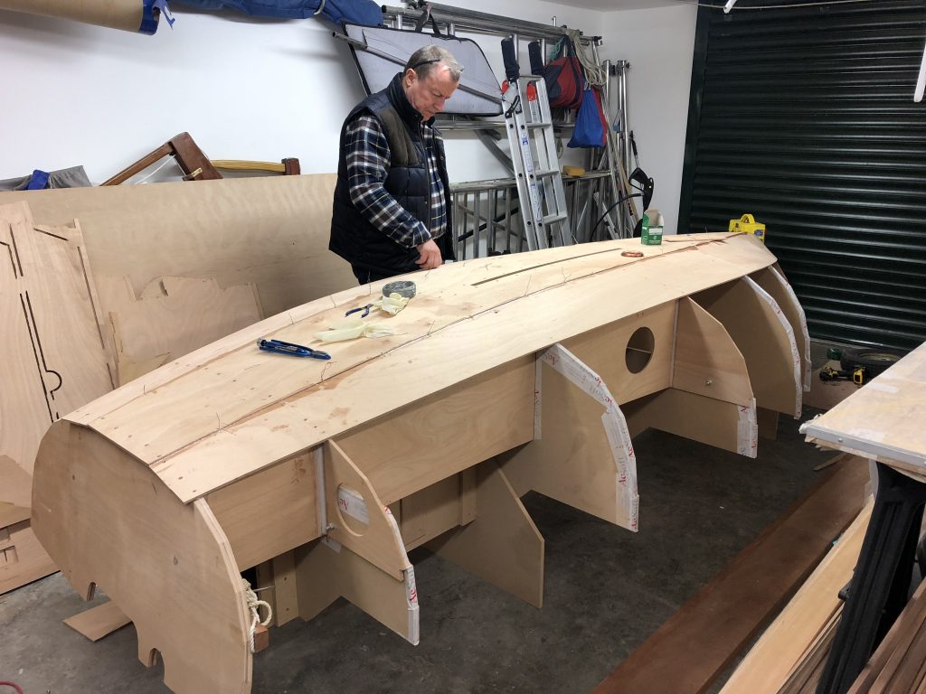
The rest was quite quick. I managed to break the back of this job while madam was away in Italy. The only trick to learn is the bevel the edge of each preceding strake, to give a good overlap for the epoxy, while making sure there’s not to much step inside the hull. The belt sander was a boon here, but I’m sure a proper boatbuilder will use a plane.
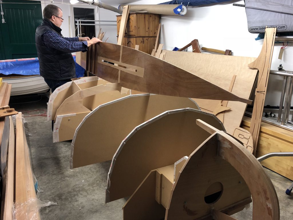
Notice I’ve also made the skeg, which you have to do yourself – there is no pattern or template in the kit, so make a cardboard template to get the curve of the sole right.
If I had to admit to a mistake, it was screwing the strakes to Station 5 before the inner stem, which meant the curve was not quite so fair – I should have read the Oughtred book once more as he warns against this. But you’ve got to look hard to see it!
Now all that remains is to fair off the overlaps at the bow (belt sander again!) and fit/trim the previously laminated outer stem
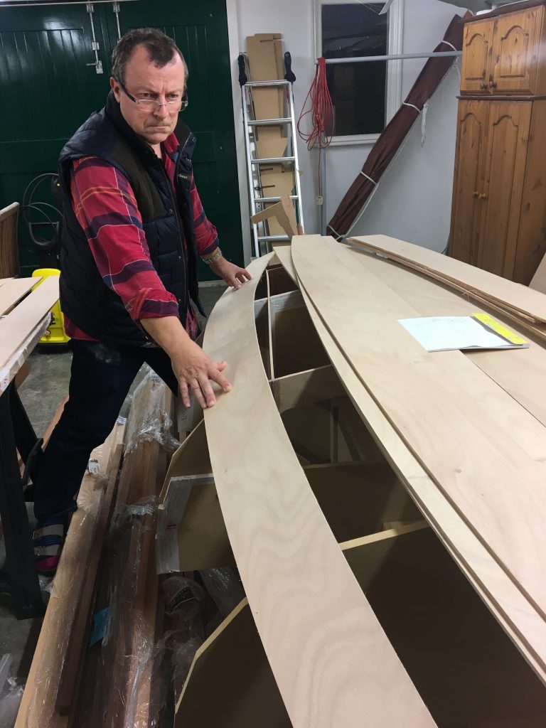
One of the nice things about building a boat is learning all the nautical terms for the bits and pieces. I must admit to be pretty clued up anyway, but I never really understood what was meant by the garboard. Now I know – it’s the next strake up from the sole.
This is where the beauty of CNC kits comes in – just by dry fitting the strake showed that everything was going to go together very neatly, with minimal fettling.
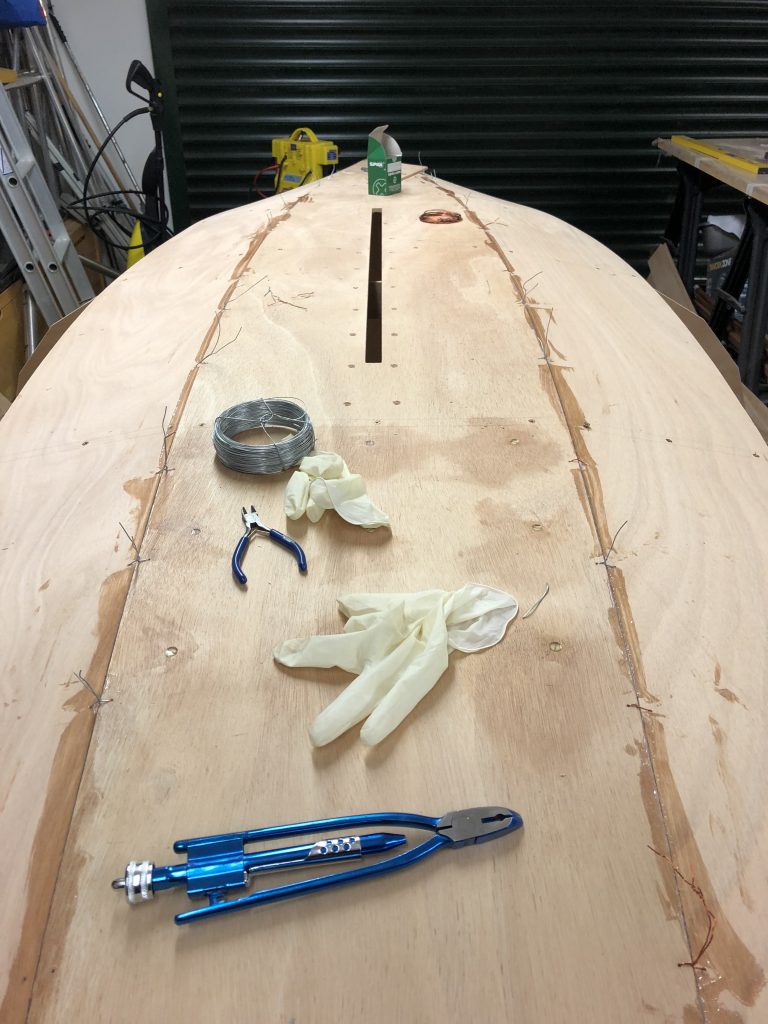
The joint between the sole and garboard is basically a butt joint, held together by stitch and glue. This is because the sole is thicker plywood than the garboard, so there’s a step at the joint. I remember the technique from when the Mirror dinghy was introduced, as it was basically used throughout. In practice the fit is so good, you can probably get away without stitching, as the joint is going to be taped afterwards. But orders is orders, so I tooled up with a handy gadget which I think was designed for fencing, but actually worked well in pulling the joint together.
The magic tool. I wonder if I’ll ever use it again!
The curve at the forward end of the strake is quite daunting, but it was not difficult to get it all screwed and glued to the inner stem with sacrificial screws.
Note the fillets on Station 1 inside the buoyancy tank
The strake can be screwed to each frame temporarily, but if I was building a varnished version, I might think of a better way of holding it all in place as per the Oughtred book.
Once the strake is glued to the longitudinal bulkheads, add some epoxy fillets on the inside of what will be the buoyancy tanks. It’s also worth getting underneath and wiping away any dribbles with acetone, otherwise it adds to the sanding work later on.
Now seemed a good time to drill and countersink the holes for the centreboard case log, otherwise that could be tricky once the hull is inverted.
You can only put it off so long. Now comes the actual boatbuilding! The first step is to fit the transom on the ends of the side tank bulkheads. The tabs fit into the slots in the transom, which means that these need to be clear of any excess epoxy from when it was laminated. Try dry fitting a few times, to make sure it fits cleanly. When it came to gluing, a did have a small issue aligning it, so ended up using a couple of Spanish windlasses to keep it square while the epoxy went off. Then add some fillets to the joint for strength.
The inner stem/Station 5 sub-assembly also needs to be fitted, with a couple of bolts to the frame.
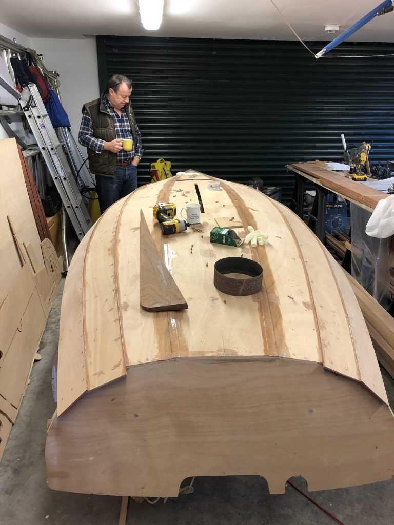
Then the sole is added. Before fitting this, I glued and screwed the foot rests in place, as I figured it would be easier now than later. I also applied the coat of epoxy and 30gsm matting to the floor, but leaving strips untouched where later joins would be made to e.g. Station 1/3 and the centreboard case.
Note that all exposed edges of the MDF frames need to be taped, to avoid any strakes sticking to them. You can see this above.
The bulkhead at Station 5, and the inner stem both need to be chamfered for later fitting of the strakes. This is best achieved with careful use of a belt sander, and some scrap ply simulating the strake.
The sole is held in position with some sacrificial screws to the frame and inner stem while setting, and they can be removed afterwards and the holes filled.
Note the chamfers on the Station 5 bulkhead. The inner stem needs to be aligned with the centreline before gluing/screwing the sole to it.
The sole is glued to the transom and bulkheads 1, 3 and 5. When cured, it’s a good idea to add fillets to the joins underneath to improve rigidity